Connecting the MiniBee and coordinator board
In order to program a MiniBee you’ll need a programmer with wires connected to the MiniBee’s GND, 3v3, RX and TX pins. You can most easily use the coordinator board of your Sense/Stage network to do the programming. This is the method that will be shown in this guide. This guide assumes you are able to do some basic soldering in order to make the four-wire programming cable.
Note: This guide applies to the latest MiniBee revisions F and D; see the MiniBee board reference if you are unsure which revision you have. The earlier revision B boards have the RX/TX pins only broken out in the middle of the PCB.*
Creating the four wire serial cable
In order to connect the coordinator board to your MiniBee’s GND, 3v3, RX and TX pins you will need to create a four-wire connection between the coordinator and the minibee. You could do this using loose jumper cables and a bit of soldering, but we prefer to make a custom cable that can easily be removed.
In order to make the four-wire cable you’ll need the following materials, note that all pin headers have 2.54mm pin spacing:
- a 4x1 pin male header
- a 2x2 pin male header
- an angled 4x1 pin female header (to attach to the coordinator)
- a four wire ribbon cable, or four pieces of hookup wire
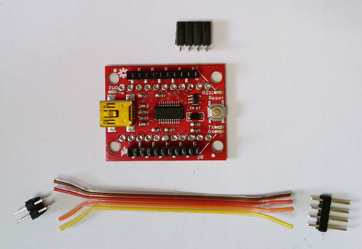 The materials you’ll need
First, solder the angled female header to these four pins.
Looking under the coordinator board, you’ll see all the through-hole solder pins marked. The four pins you will connect to on the coordinator board are GND 3.3V DOUT and DIN ~ connect the 4-pin header to these pins.
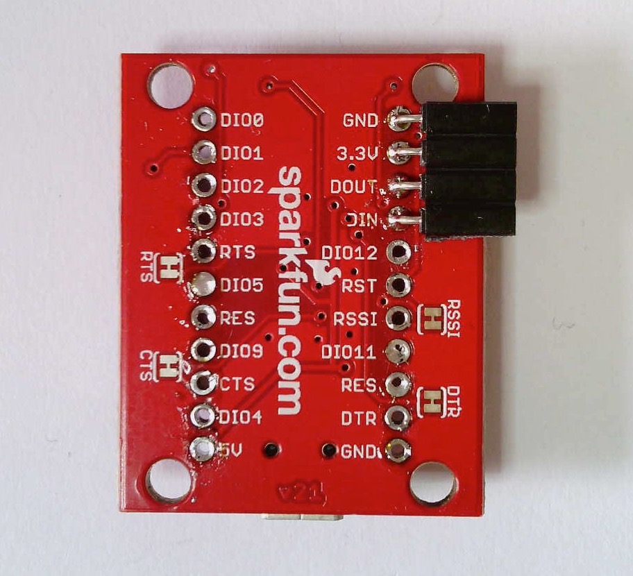 4-pin female header soldered to the GND, 3.3V, DOUT and DIN pins of the coordinator
Making the connecting cable
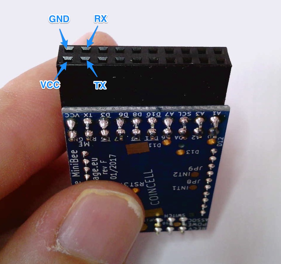
Now you’ll need to make a cable connecting these four pins to four pins on the MiniBee. If you look under the MiniBee (where the header attaches) you’ll see the pins labeled. The pins you will connect to on the MiniBee are GND VCC TX and RX ~ these four pins are in a 2x2 pattern, which you will use the 2x2 header to connect into.
Go ahead and solder the cable. Be very careful that the wires are connected correctly at the two ends. We also recommended that you use a clear color coding for the wires. In the photographs below, we are using: red = 3v3, black = GND, orange = DOUT/TX, yellow = DIN/RX.
Make the pin connections from the coordinator to the MiniBee as follows:
GND -> GND
3.3V -> VCC
DOUT -> TX
DIN -> RX
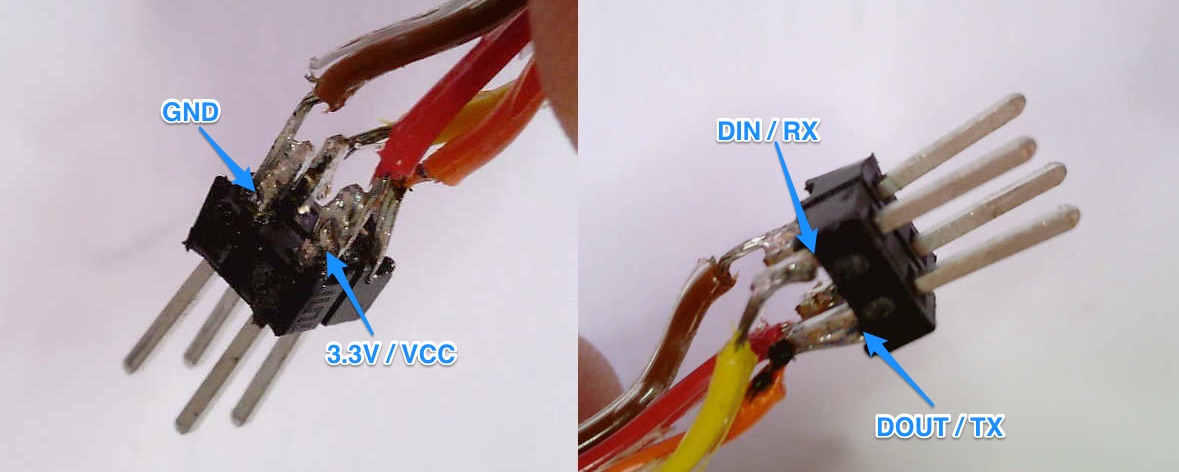 Wires attached to the 2x2 header
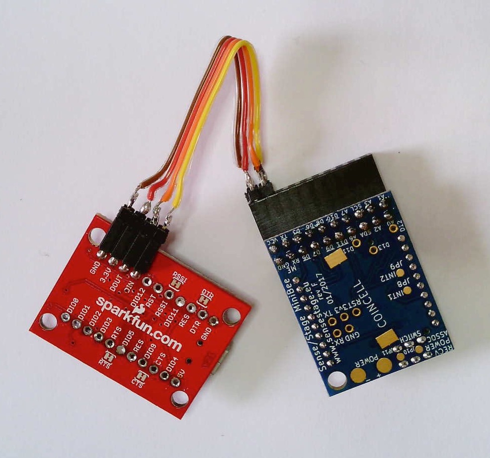 The finished cable, connecting the coordinator to the MiniBee
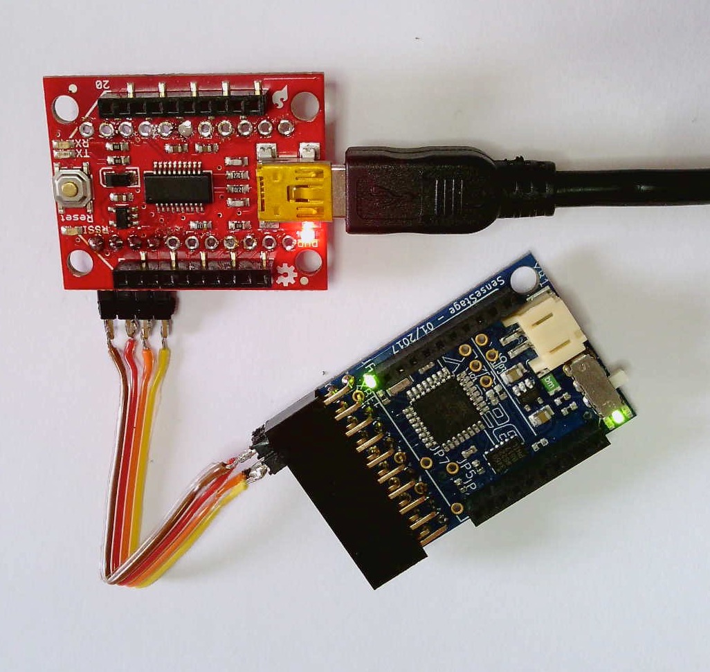
Connect the Coordinator to your computer
Now that you’ve made the serial programmer cable. Connect the coordinator to your computer’s USB port, and connect the MiniBee to the coordinator using the cable you just made. The MiniBee’s green power LED should turn on, indicating that it is receiving power from the coordinator board.
In the next step you’ll configure the Arduino IDE with appropriate hardware profiles to be able to detect and program your MiniBees.