MiniBee Board Reference
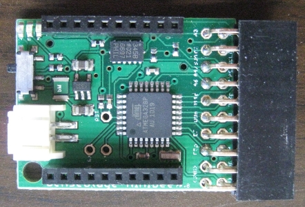
The Sense/Stage MiniBee is a small microcontroller sensor board based on the Arduino, which is intended to be integrated with an XBee wireless communications chip. It is small and comes with preloaded firmware to use it easily in your wireless projects and is compatible with most common sensing and actuating purposes.
As a bonus there is a 3-axis accelerometer on board. So you can already start capturing movement measurements right out of the box.
There have been four revisions of the MiniBee board, each with small improvements to the hardware. The revision number will be printed on the bottom side of your MiniBee. The latest revision is F, which has a blue colored PCB instead of the green colored PCBs of previous versions.
Overview of the features:
- 6 analog inputs: A0, A1, A2, A3, A6, A7
- 8 digital inputs or outputs: D3, D5, D6, D7, D8, D9, D10, D11; or optional four more: A0, A1, A2, A3
- PWM (“analog”) output, at pins D3, D5, D6, D9, D10, D11
- TWI (or I2C) communication: SDA (A4), SCL (A5)
- Integrated ADXL345 – 3-axis accelerometer
- Serial I/O: RX, TX (to XBee)
- Power input (between 3.3V and 5V), through battery connector and coin cell battery
- Regulated power output: 3.3V, GND
- On/off switch
- Short circuit protection with a resetting fuse
- Status LEDs for power, association with XBee network, XBee receiving data, and configuration status
- Small footprint
- Preprogrammed with firmware for wireless configuration for using many common sensors
- Firmware communication with software data sharing network supported by many common interactive software environments (e.g. SuperCollider, Max/MSP, PureData, Processing).
The different versions:
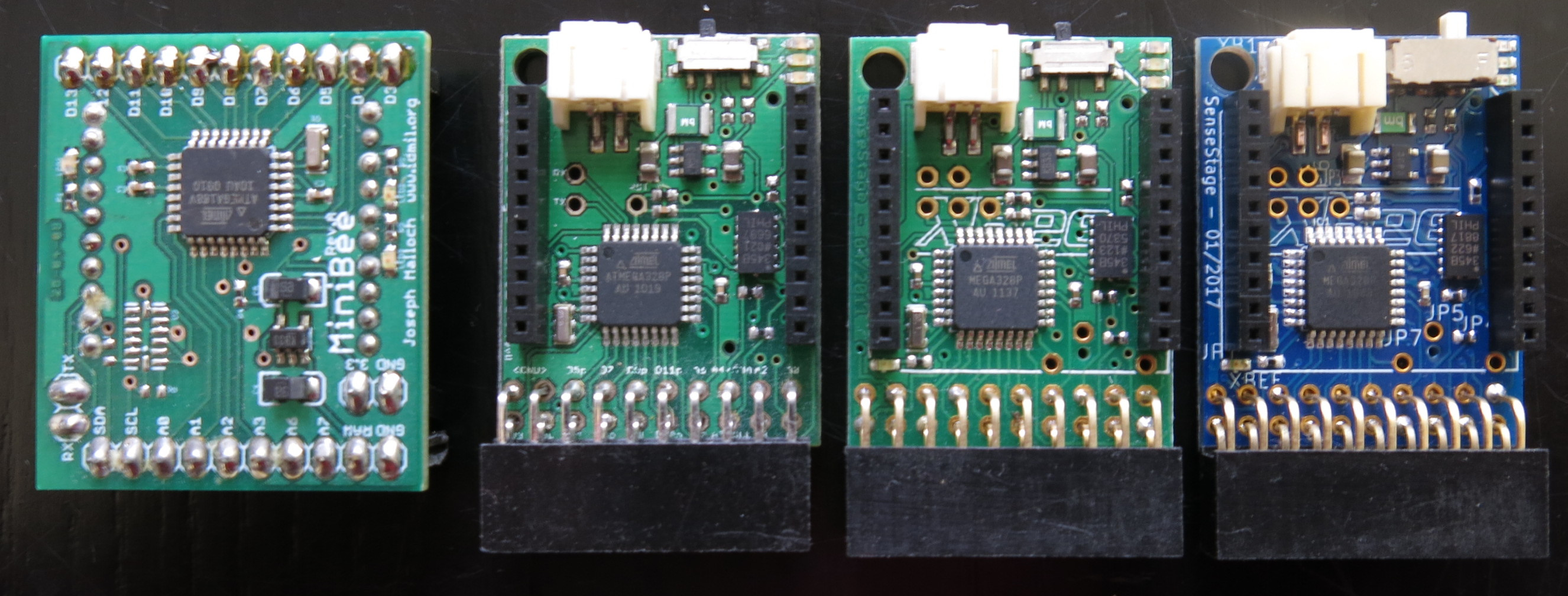 From left to right: MiniBee revisions A, B, D and F
| page created on: | last changed on: |
|---|---|
| 6 February 2017 | 4 September 2019 |