The electronic schematic
To connect the haptic motor, you will need the following components:
- a NPN transistor, for example the 2N3904
- a diode, for example the 1N4007
- optionally, a capacitor of ca. 0.1uF
- two resistors, we have used 1kOhm and 330 Ohm with the components mentioned above
The schematic for connecting these components is shown below:
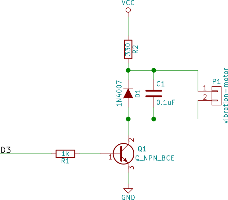
- D3 is the pin of the MiniBee to connect to. This can be any of the available pins that can do PWM: D3, D5, D6, D9, D10 or D11.
- The resistor R1, in the schematic with the value 1kOhm, is necessary to limit the current that will flow into the transistor. If too much current flows in, then the transistor might break.
- The diode D1, in the schematic we have used the general purpose diode 1N4007. This diode is called a ‘flywheel diode’. It is necessary because a vibration motor is an inductive load, and omitting the diode might cause irregularities in the power supply, which can cause components to break. It is important to take note of in which direction you connec the diode. The schematic symbol for a diode consists of a triangle and a line. Usually on the component itself also a line is drawn on one end of the component, this line corresponds to the line in the symbol.
- The resistor R2, this resistor limits the amount of current that will flow through the haptic motor. We found 330 Ohm was a good value with the components that we used.
- The capacitor C1, in parallel with the diode D1. This capacitor is optional, but we found that adding it in the circuit improved the behaviour. It will slow down the switching slightly and smooth out the changes in vibration of the motor. We used a value of 0.1uF or 100 nF.
- The haptic motor is then connected in parallel with the diode (and the capacitor).
- Q1 is the NPN-transistor. The NPN transistor has three inputs:
- the base - in the schematic the pin pointing to the left and connected to resistor R1,
- the emitter - in the schematic the pin pointing down and connected to ground,
- the collector - in the schematic the pin pointing up and connected to the diode, capacitor and vibration motor.
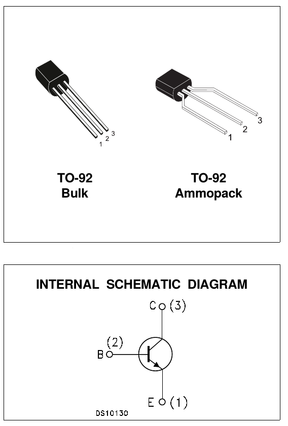
Which physical pins these are on the device can vary per transistor, so you will have to look up the datasheet of your transistor (if you type in a search engine the type number (e.g. 2N3904) and ‘datasheet’, you will normally find the PDF of the datasheet easily). On the datasheet there will be a diagram like below, with the schematic symbol and an image of the component indicating which pin is which, or describing which pin is which in a list of pin number (indicated in the image which pin has which number) and what is the collector (C), base (B) and emitter (E).
More information on how to select the resistors can be found in this tutorial: Transistor as a switch on another website.