Soldering the electronics on an XPree board
The next step is to solder the electronics together, for example on an XPree board. In the images on this page you will see an example of what that can look like.
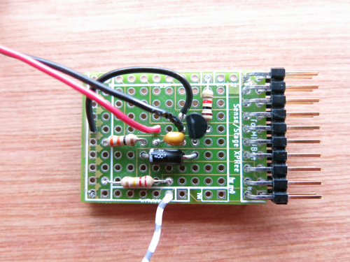
In the top view you can see how the components are laid out. The 1k resistor (R1 : brown-red-black - gold) goes from the top row, the hole that is labeled D3 to the second pin of the transistor.
The top pin of the transistor (pin 1 according to the datasheet) is connected to ground with the black wire.
The capacitor, diode, and the black wire that goes to the vibration motor are connected on one side (right) to pin 3 (the lowest one) of the transistor. On the other side, they are connected to the resistor (R2 : orange-orange-black - gold).
The resistor R2 is connected on the other side to 3v3, or Vcc.
The other resistor and wire at the bottom of the photo are not relevant for this tutorial - they were used to connect a resistive sensor to an analog input
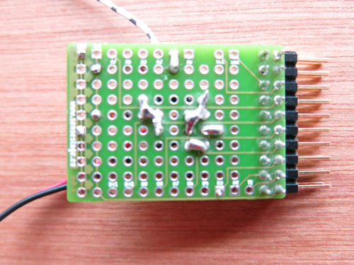
If we flip the board around, we can see the connections soldered at the bottom. What was at the top of the image in the view from above, is at the bottom of the image in the view from below.
Thus, at the top of this picture are resistor and wire for the resistive sensor that is not relevant to this tutorial.