Implementing message confirmation
The XBee itself already implements a system for message confirmation and resending, but sometimes this is not enough. If there is a lot of data going back and forth over the wireless network, messages may still get lost in the air.
Then implementing your own system on top of that to confirm that messages were received can be a solution.
The general approach is this:
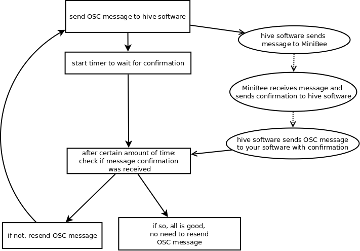
- you send out an OSC message from your software to the hive software
- the hive software sends a message to the MiniBee
- the MiniBee firmware receives the message, and sends a message back to the hive software to confirm what it received
- the hive software sends an OSC message to your software with that confirmation
In your own software you then implement what your system will do if after a certain time it has not yet received confirmation. For example, in the flowchart below (the rectangular block are what your software does; the ellipsoids are what the Sense/Stage system takes care of), the software will resend the OSC message if no confirmation was received after a certain amount of time.
Adapting the firmware
To adapt the firmware, we need to implement a custom message receiver that will:
- send a message back to the hive software, and
- use the contents of the message to execute the desired action
For example:
// Use pin D3 for controlling the vibration motor
#define VIBRATION_PIN 3


/// this will be our parser for the custom messages we will send:
/// msg[0] and msg[1] will be msg type ('E') and message ID
/// the remainder are the actual contents of the message

void customMsgParser( uint8_t * msg, uint8_t size, uint16_t source ){
    // loopback the message to check!
    analogWrite( VIBRATION_PIN, msg[2] );
    Bee.sendPrivateData( msg, size, true );
}
In this example, the message parser will use the msg[2], the first data value of the message, to set the vibration intensity with AnalogWrite. Then it sends back the exact same message it receives with the function: Bee.sendPrivateData.
In the setup function of the firmware, you need to enable the customMsgParser and define the pin VIBRATION_PIN as a custom pin.
void setup() {
  Bee.setup(57600, 'D' ); // arguments are the baudrate, and the board revision (`D` or `F`)

  // define which pins we will be using for our custom functionality:
  // arguments are: pin number, size of data they will produce (in bytes)
  // in our case, pin 3 and we don't output any data from this pin
  Bee.setCustomPin( VIBRATION_PIN, 0 );

  // set the custom message function
  Bee.setCustomCall( &customMsgParser );
}
Then finally, in the loop function of the firmware, we make sure that the firmware checks as often as possible the data it receives, after the initial startup of the MiniBee.
void loop() {
    uint8_t bee_status;
    for ( uint8_t i=0; i<20; i++ ){
        Bee.loopReadOnly(); // only read incoming serial data
        bee_status = Bee.getStatus(); // check the status of the MiniBee
        if ( (bee_status == SENSING) || ( bee_status == ACTING ) ){
            delay(1); // if the MiniBee is up and running, only wait 1 ms for the next message
        } else {
            delay(20); // if the MiniBee is still being configured, wait 20 ms for the next message
        }
    }

    // do a full 'loopstep', including sensing, but dont' let the firmware library insert delays
    // (we do that ourselves in this firmware)
    Bee.loopStep( false );

    bee_status = Bee.getStatus(); // check the status of the MiniBee
    if ( (bee_status == SENSING) || ( bee_status == ACTING ) ){
        delay(1);  // if the MiniBee is up and running, only wait 1 ms for the next message
    } else {
        delay(20); // if the MiniBee is still being configured, wait 20 ms for the next message
    }
}
In this loop, once the MiniBee is configured by the hive software, the firmware will check for incoming messages every 1ms. Every 21 ms (after the code in the for loop has been run 20 times), the firmware will also do whichever sensing and other default functions were configured through the hive software.
TODO: link to [full firmware file for this example]
The OSC messages to send and to receive
Instead of using the normal /minibee/output OSC message, you will now need to send a custom OSC message:
/minibee/custom 2 255will turn the motor/LED fully on./minibee/custom 2 0will turn the motor/LED fully off./minibee/custom 2 127will turn the motor/LED on at half strength.
The OSC message you will receive back as confirmation for the first message is /minibee/private 2 69 0 255:
2is the MiniBee id,69is the ascii code forEwhich is used as the identifier for a custom message,0is the message id, this number will go up from 0 to 255 and then wrap back to 0. So for the second message you send out the confirmation will be:/minibee/private 2 69 1 255. You can use this counter also to check if a message got lost or to analyse how many messages are getting lost.255was the value that you sent, so for the second example (fully off) the message would be:/minibee/private 2 69 1 0
So in the check for confirmation in your software you use and compare:
- the minibee id - this needs to match the one your OSC message was intended for
- the value(s) that you sent - this should match the content of the OSC message you sent
- optionally, you can make use of the message id to check how many messages get lost