MiniBee DIY - use your own Arduino and XBee
This page describes how to make use of the MiniBee firmware with your own Arduino and XBee combination.
| sensestage-v1 | > | hardware | > | minibee | tags: |
The Sense/Stage MiniBee is a small microcontroller board based on the Arduino, integrated with a connection for an XBee wireless chip. It is small and comes with preloaded firmware to use it easily in your wireless projects for a lot of common sensing and actuating purposes. As a bonus there is a 3-axis accelerometer on board. Cross platform open source software sends the data from the boards to your interactive environment via OpenSoundControl (OSC).
If you do not have access to one of the SenseStage MiniBees, you can still use our firmware if you create your own Arduino and XBee combination.
Connections
Our firmware assumes that the connections between the Arduino and XBee are as follows:
- Pin D7 on the Arduino is connected to pin 9 (DTR/SLEEP_RQ) of the XBee. (In revision D, pin D2 was connected to pin 9 of the XBee).
- Pin D0 (RX) on the Arduino is connected to pin 2 (DOUT) of the XBee.
- Pin D1 (TX) on the Arduino is connected to pin 3 (DIN) of the XBee.
- Pins 13 (ON,SLEEP), 6 (RSSI) and 15 (ASSOC) on the XBee are useful to connect LEDs to in order to see what is going on.
- Pin 1 is Vcc on the XBee and should be connected to 3.3V; pin 10 is GND and should be connected to ground.
General notes
- While programming the firmware onto the Arduino, you have to remove the XBee from the board, as otherwise the firmware upload will not work.
- Arduino variants with the ATmega328p chip work best with the firmware, as it has more memory.
- Use the XBee series 1 chip (either the regular one or the Pro version; with any antenna type you like).
Programming firmware
For programming the firmware, use the board definition for the Arduino that you are using.
In the source code of the firmware, make sure that you use revision D if you have made the connection from D2 to the sleep pin of the XBee, so the Bee.setup command should be:
Bee.setup(57600,'D');
If you have made the connection from D7 to the sleep pin of the XBee, make sure that you use revision F in the firmware:
Bee.setup(57600,'F');
Arduino Fio
(tested succesfully)
On the Arduino Fio (which is another board including a footprint for the XBee) all you need to connect is pin D7 (or D2) to the DTR pin/hole in the middle of the board, as shown in the picture (confusingly, there is another pin on the opposite side of where D2 is that is also called DTR, this is not the right one though); all of the other connections are made, so you can just stick on your XBee.
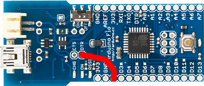 Showing how to make the connection between pin D2 and DTR of the XBee on the Arduino Fio. Program the firmware as if using MiniBee revision ‘D’.
Arduino with XBee Shield
(tested succesfully with some shields)
The Sparkfun Arduino XBee shield already has a couple of pins connected in the right way. These are the modifications you need to make in addition:
- Connect pin D2 (or D7) on the Arduino to pin 9 (DTR/SLEEP_RQ) of the XBee.
- Set the switch on the shield to UART. This takes care of the RX/TX lines from the Arduino to go to the XBee.
- Connect an LED with a resistor to pin 13 (ON,SLEEP) of the XBee. The other pins (6 and 15) already have LEDs on them.
- The power connections are already in place.
The Libelium Arduino XBeeShield has some unfortunate design choices, which cause the Arduino to reset when the XBee sleeps. We have not gotten it to work with the SenseStage MiniBee firmware.
Lilypad with Lilypad XBee board
(not yet tested)
The LilyPad XBee board already has a couple of pins connected in the right way. These are the modifications you need to make:
- Pin D2/D7 (slp) on the LilyPad is connected to the DTR of the LilyPad XBee.
- Pin D0 (RX) on the LilyPad is connected to the RX of the Lilypad XBee.
- Pin D1 (TX) on the LilyPad is connected to the TX of the Lilypad XBee.
- Pins 13 (ON,SLEEP) and 6 (RSSI) already have LEDs connected. Pin 15 (asc) on the LilyPad XBee could have another LED/resistor.
- 3.3V on the LilyPad XBee and should be connected to 3.3V of the LilyPad; “-” is GND and should be connected to ground on the LilyPad.
Arduino with an XBee breakout board
(tested succesfully)
Make the connections as described at the top.
| sensestage-v1 | > | hardware | > | minibee | tags: |
| page created on: | last changed on: |
|---|---|
| 6 February 2017 | 4 September 2019 |