MiniBee Revision A
The MiniBee revision A was the first version of the MiniBee, the alpha version. It was manufactured during the research-creation project Sense/Stage at Concordia University and McGill University in 2009.
| minibee | hardware | minibee | battery | coordinator | expansion | xbee |
| tags |
The Sense/Stage MiniBee is a small microcontroller board based on the Arduino, integrated with a connection for an XBee wireless chip. It is small and comes with preloaded firmware to use it easily in your wireless projects for a lot of common sensing and actuating purposes. As a bonus there is a 3-axis accelerometer on board. Cross platform open source software sends the data from the boards to your interactive environment via OpenSoundControl (OSC).
It was only distributed to those who were somehow involved in the project. The overview of the board is given here for historical reference.
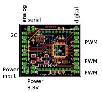
- 8 analog inputs (left side): A4 (SDA), A5 (SCL), A0, A1, A2, A3, A6, A7
- 11 digital inputs or outputs (right side): D3 to D13
- PWM (“analog”) output, (right side), D3, D5, D6, D9, D10, D11
- I2C communication, (left side top): SDA, SCL
- Serial I/O (top left): RX, TX
- Power input (between 3.3V and 5V) (left side bottom): RAW, GND
- Regulated power output (left side bottom inside): 3.3V, GND
- green pcb
Pin out
LEDs
Technical documents
- board layout
- schematic
Design files for Eagle on github
Programming firmware
For programming the firmware, use the board definition: Sense/Stage MiniBee revA (3.3V, 8MHz) w/ Atmega168
Programming the bootloader
Before the firmware can be uploaded to the board, a bootloader needs to be present on the board. This section describes how the bootloader can be programmed onto the board. This only needs to be done once; depending on how you obtained your board, the bootloader may already have been programmed onto the board.
Soldering:
- 2 pin female header to RX/TX
- 2 pin female header to 3.3V / GND
- female headers to pin D11, D12, D13
You need:
- A programmer board to fit the board on
- A USB adapter
- AVR mkII – avr programmer
While programming the bootloader, you must hold a wire to the reset pin. This is to work around an omission in the revA design.
Use the Arduino programming software:
- Set the board type to
Sense/Stage MiniBee revA (3.3V, 8MHz) w/ Atmega168 - Choose
Program BootloaderwithAVR ISP mkII - On Ubuntu Linux you must run the Arduino software as root in order to do this
TODO
- add pinout
- add note about LEDs
Related pages:
| minibee | hardware | minibee | battery | coordinator | expansion | xbee |
| tags |
| page created on: | last changed on: |
|---|---|
| 6 February 2017 | 6 February 2018 |