MiniBee Revision F
The MiniBee revision F is the fourth version of the MiniBee, the second production version. It is manufactured and sold from 2017.
| sensestage-v1 | > | hardware | > | minibee | tags: |
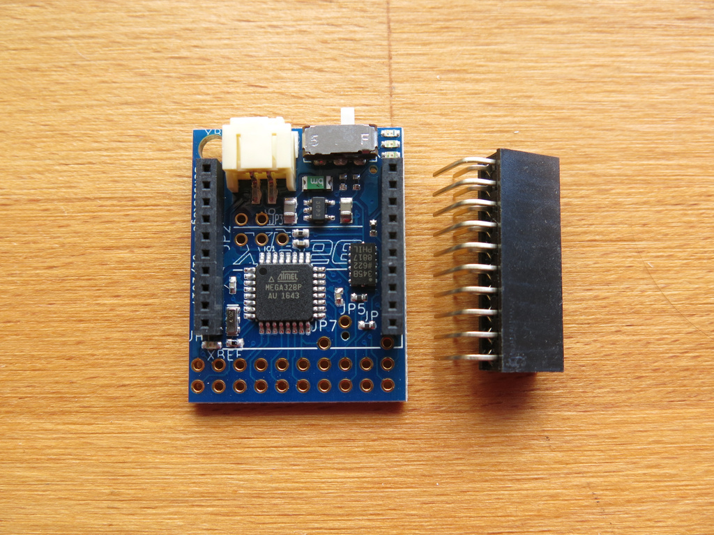
The Sense/Stage MiniBee is a small microcontroller board based on the Arduino, integrated with a connection for an XBee wireless chip. It is small and comes with preloaded firmware to use it easily in your wireless projects for a lot of common sensing and actuating purposes. As a bonus there is a 3-axis accelerometer on board. Cross platform open source software sends the data from the boards to your interactive environment via OpenSoundControl (OSC).
The MiniBee revision F is the fourth version of the MiniBee, the second production version. It is manufactured and sold from 2017.
Overview of the board:
- 6 analog inputs: A0, A1, A2, A3, A6, A7
- 8 digital inputs or outputs: D2, D3, D5, D6 and D8 to D11
- PWM (“analog”) output, at pins D3, D5, D6, D9, D10, D11
- I2C communication: SDA (A4), SCL (A5)
- Serial I/O: RX, TX (to XBee)
- Power input (between 3.3V and 16V), through battery connector and coin cell battery
- Regulated power output: 3.3V, GND
- blue pcb
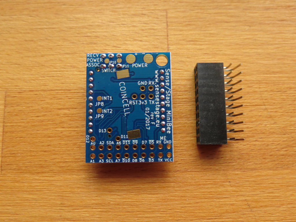
Pin out
The pin outs on the header are from left to right:
GND - RX - D5 - D2 - D9 - D11 - A6 - SDA - A2 - A0
3v3 - TX - D3 - D6 - D8 - D10 - A7 - SCL - A3 - A1
On the bottom of the board, the pin labels are also printed. By mistake pin D2 is labeled as D7.
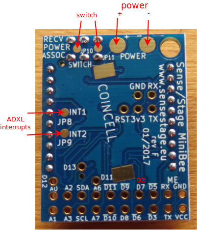
Bottom pads
On the bottom of the board, a couple of pads are broken out:
- POWER
+and- - two pads for adding your own external switch
INT1andINT2of the ADXL345
LEDs
There are four LEDs on the MiniBee revision D:
- a red LED to indicate that the MiniBee is receiving data from the coordinator node. This one only goes on for about a second, when the XBee is receiving data.
- a green LED to indicate that the MiniBee is on. This one will be on if you have switched the power on.
- an orange LED to indicate that the XBee is associating with a network and that it is on. This one will be blinking.
- a green LED is just between the XBee header and the extension header. This one is used inside the firmware to indicate that the module is sending out data.
Technical documents
Board layout and schematic are available here: design files for KiCad on github
Changes to previous version
Revision F of the board has a few improvements on revision D based on the feedback from users:
- a blue pcb to distinguish it easily from previous revisions
- a different on/off switch, which is both mechanically and electronically more sturdy
- a 300 mA voltage regulator instead of 150 mA
- pads on the bottom that break out power supply, the on/off switch, and the interrupt pins of the accelerometer
- an exchange of pin D2 and D7 - so that the interrupt capability of D2 can be used by the user; pin D2 takes the place of pin D7 in the configuration file
Also the design has been moved from the (closed source) Eagle software to the open source Kicad software, so that the design of this open source hardware module is now also made with open source software.
Programming firmware and the bootloader
For programming the firmware, use the board definition: Sense/Stage MiniBee revB/D/F (3.3V, 12MHz) w/ Atmega328p
In the source code of customized firmware, make sure that you use revision F, so the Bee.setup command should be:
Bee.setup(57600,'F');
Related pages:
| sensestage-v1 | > | hardware | > | minibee | tags: |
| page created on: | last changed on: |
|---|---|
| 6 February 2017 | 28 March 2018 |