MiniBee Revision D
The MiniBee revision D was the third version of the MiniBee, the production version. It was manufactured and sold between 2011 and 2016.
| sensestage-v1 | > | hardware | > | minibee | tags: |
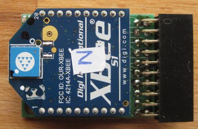
The Sense/Stage MiniBee is a small microcontroller board based on the Arduino, integrated with a connection for an XBee wireless chip. It is small and comes with preloaded firmware to use it easily in your wireless projects for a lot of common sensing and actuating purposes. As a bonus there is a 3-axis accelerometer on board. Cross platform open source software sends the data from the boards to your interactive environment via OpenSoundControl (OSC).
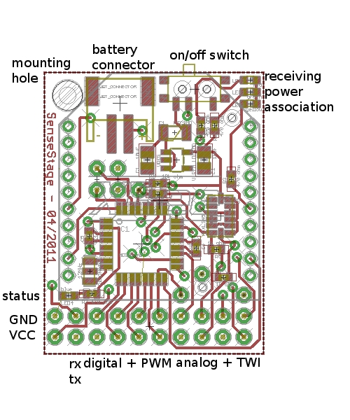
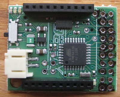
Overview of the board:
- 6 analog inputs: A0, A1, A2, A3, A6, A7
- 8 digital inputs or outputs: D3 and D5 to D11
- PWM (“analog”) output, at pins D3, D5, D6, D9, D10, D11
- I2C communication: SDA (A4), SCL (A5)
- Serial I/O: RX, TX (to XBee)
- Power input (between 3.3V and 5V), through battery connector and coin cell battery
- Regulated power output: 3.3V, GND
- green pcb
Pins
The pin outs on the header are from left to right:
GND - RX - D5 - D7 - D9 - D11 - A6 - SDA - A2 - A0
3v3 - TX - D3 - D6 - D8 - D10 - A7 - SCL - A3 - A1
LEDs
There are four LEDs on the MiniBee revision D:
- a red LED to indicate that the MiniBee is receiving data from the coordinator node. This one only goes on for about a second, when the XBee is receiving data.
- a green LED to indicate that the MiniBee is on. This one will be on if you have switched the power on.
- an orange LED to indicate that the XBee is associating with a network and that it is on. This one will be blinking.
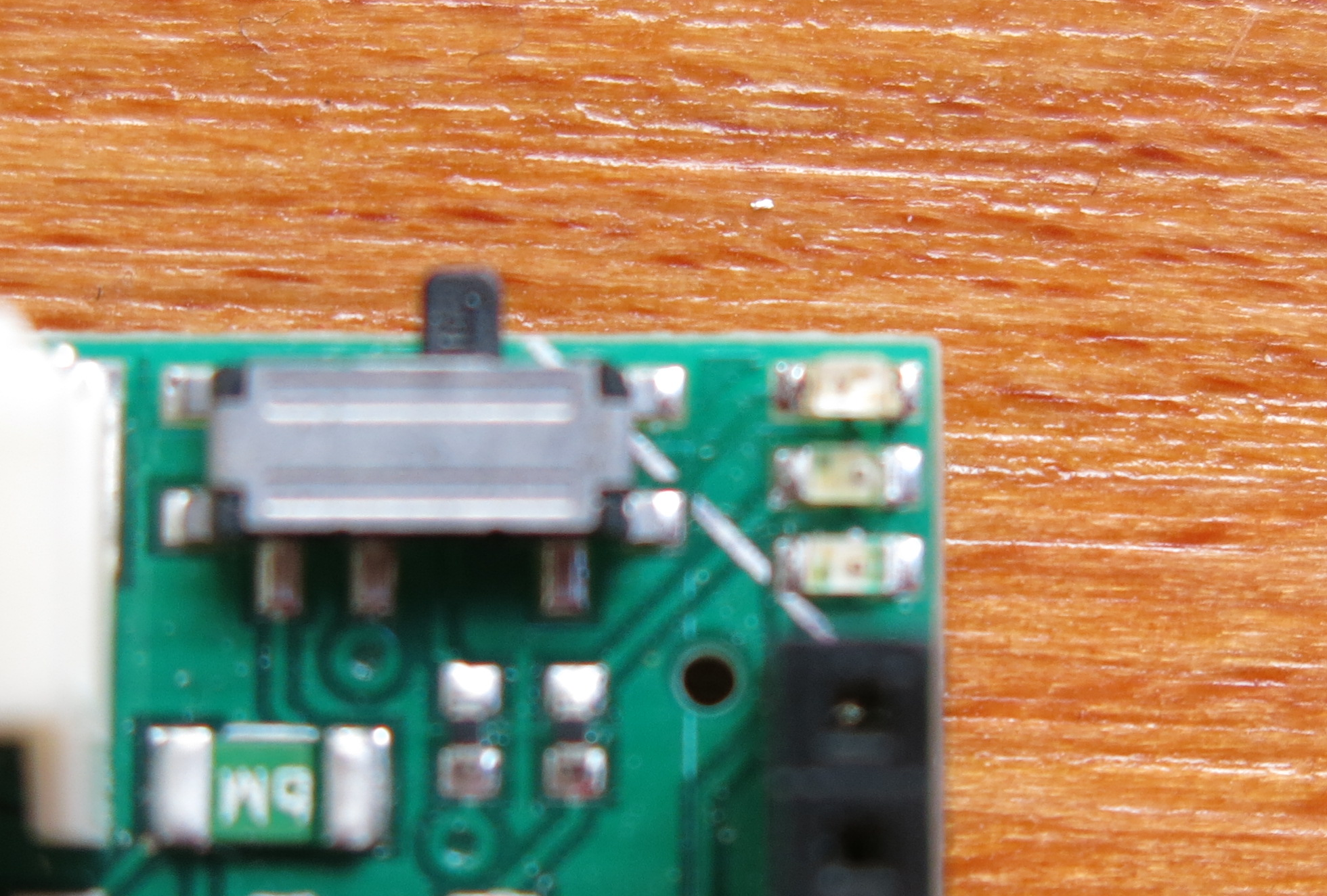 LEDs for receiving data, power, association (xbee on)
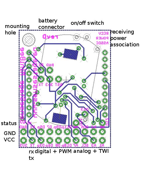
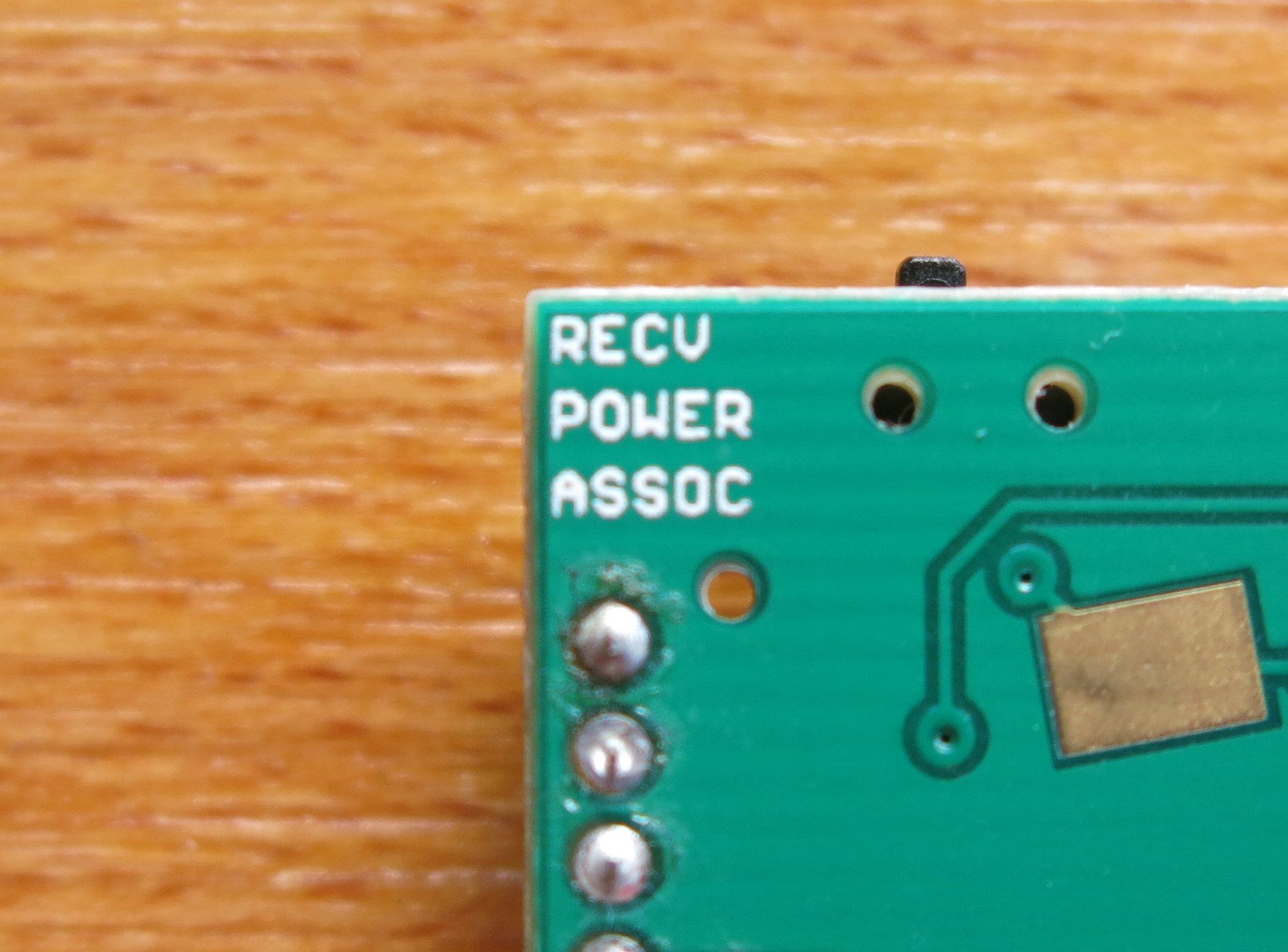 labels on the back for receiving data, power, association (xbee on)
- a green LED is just between the XBee header and the extension header. This one is used inside the firmware to indicate that the module is sending out data.
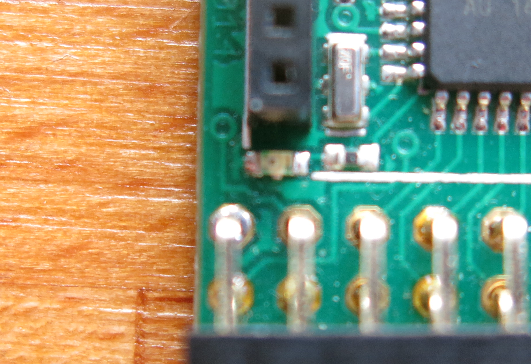 status LED near the header
Technical documents
Board layout and schematic are available here: design files for Eagle on github
Changes to previous version
Revision D of the board has a few minor improvements on revision B:
- An additional LED on pin D4 for status indication.
- RX and TX also available on the output pin header.
- All bootloader programming pins broken out in the middle of the board
Programming firmware and the bootloader
For programming the firmware, use the board definition: Sense/Stage MiniBee revB/D/F (3.3V, 12MHz) w/ Atmega328p
In the source code of customized firmware, make sure that you use revision D, so the Bee.setup command should be:
Bee.setup(57600,'D');
Subversions
The first manufacturing run has the Atmega328 chip instead of the Atmega328p chip. This is a subtle difference that only affects the board if you want to program the bootloader onto the board, or program firmware without using the bootloader. The boards of this first batch can be recognized by a sticker on the bottom with a serial number, and the desoldered pin holes. In the hardware definitions within the Arduino IDE, this version is called Sense/Stage MiniBee revD0 (3.3V, 12MHz) w/ Atmega328. You only need this for programming the bootloader or programming the board with the Atmel programmer, not for the regular uploading of firmware.

You may also need this section in the avrdude.conf file that is in the hardware/tools/ folder of your copy of Arduino if you want to program with an AVR programmer onto the chip (e.g. for changing the bootloader, or bypassing it):
Related pages:
| sensestage-v1 | > | hardware | > | minibee | tags: |
| page created on: | last changed on: |
|---|---|
| 6 February 2017 | 28 March 2018 |