Connecting a light resistor to a MiniBee
The electronics
A light sensor is a variable resistor. In order to connect it to the MiniBee, you need to make a voltage divider:
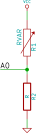
In this picture, RVAR (VARiable Resistor) is the light sensor, and R is another resistor with which you are creating the voltage divider. In this setup, the current will flow from Vcc to GND, and the voltage will be divided over RVAR and R. The voltage is measured by the MiniBee at A0. The voltage will vary, as RVAR will vary – in the case of our light sensor, it depends on the amount of light that is falling onto the sensor.
To calculate the best (i.e. the value that results in the widest range of voltage) value for the resistor R, you can do the following:
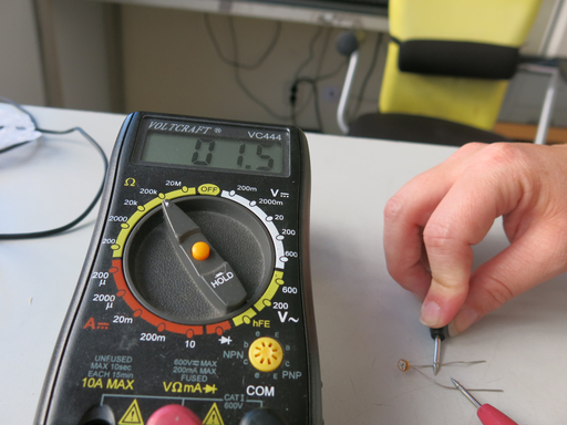
- Measure the value of the resistance of the light sensor in full darkness – Rdark
- Measure the value of the resistance of the light sensor in full brightness – Rlight
- Multiply the two values measured (Rdark * Rlight)
- Take the square root of this
- Take a resistor that has a resistance value close to this calculated value
As an example, for our light sensor, we measure 35kOhm for full brightness, and 3.5 kOhm for full darkness. 35 * 3.5 = 122.5 kOhm. The square root is: 11.068 kOhm. In our resistor box we have resistors of 10kOhm and 15kOhm. We choose the 10kOhm resistor for R.
In order to connect it to a MiniBee, we need to connect to one of the analog inputs of the MiniBee, i.e. A0, A1, A2, A3, A6 or A7.
For this, we can make use of one of the expansion boards of the MiniBee, the XPree, or XPee.